Pages

Saturday, 21 November 2015

How I made my own "designer" Straight Morse Key

After doing so many refurbishments, and the alterations to the Welsh Torsion Bar Straight Key ( My New Morse Key ).... I thought I might have a go at making my own designer straight morse key... and so the story begins.... My initial thoughts were for it to be similar to the Kent style key.. with the ball races for the pivot point... so I decided on the size of the bearings, by starting with the actual pivot rod size, which would have to be 6mm or 1/4inch round brass stock... I looked on ebay for some "cheap" bearings, as I did not know what the outcome of my work would be... i.e. if I decided that I could not proceed, then the bearing price would have been "in the bin" along with any other materials.

 I found a real bargain.... a pack of 10 bearings, 6 x 19 x 6mm for just under £4.00 including posting ! ! ..  ( http://stores.ebay.co.uk/heavends?_trksid=p2047675.l2563 )

As I did not have a workshop, the next problem I had to solve, was how and where, was I going to do the work necessary, to produce the morse key...  Fortunately, we have a BIG "shed" at the bottom of the garden.. that we only used for storage... it had power for an electric drill, lighting, and heating.. It also had a fridge in a small corner area... here, I used my imagination, and used a  couple of wooden pasting tables...  One as the base of the work bench, laid on top of the fridge, and the other to act as the "floating end" legs, by using it in an "inverted V" formation,... I used a couple of big nails to nail it together, and it became quite firm... On top of that, I used a couple of loft flooring boards for the actual workbench surface... ensuring that there was an overlap at the front and the end, for attaching a clamp on vice.  .
The Workshop !... showing the Pillar drill stand with home made sliding work table.

Next I decided I needed to have a "Pillar Drill Stand".. to fit my electric drill into, so I could drill vertially and accurately into the work pieces... This item cost me just under £25.00 from a local hardware shop.... about the same price on Ebay, but I do like to help out the small local hardware shop when I can...  .. Once I had it at home, I made a sliding work table, out of some white melamine shelving boards,........


  and another, separate one with a screwed down mini vice, to hold any work pieces that needed drill or grinding work...

View of the "sliding mini vice" work table

End on view of the sliding mini vice work table. 

A set of 4 small grinding wheels, to fit into the drill chuck, and some router bits, were added to the tools list, and also I obtained a set of Tap & Die, to make the screw threads in the work pieces as needed.  I already had drill bits, hacksaws, files, hammers etc..  so, now I was ready to start work...

My orignal design, was to use a kind of "sliding wedge" at the rear end of the rocker, to adjust the gap, but because of my limited experience of working with metal, I could not make the system work, so I abandoned that, in favour of a "flat tounge" with a screw down adjuster.

I started off with the pivot housing, through which the 1/4 inch brass round stock would go,  and ground the semi-circular parts for the housing, giving it a nice appearance.  This took some time, as I had to be very careful not to try to take too much of a "bite" with the grinding wheel.


Cutting the block, and marking up


Setting the piece on a wood block for grinding
Final location and marking for the grinding process
Fixing the block on the worktable ready for grinding with the pillar drill
Two views of the finished block


  After that, the next part was to decide where it would be fitted along the rocker arm base....


Laid on it`s side on the bench to decide on the location of the pivot block in relation to the other parts
  .......................and drill holes in the rocker arm base, and also into the pivot housing,


 then using the appropriate tap, put a thread into the pivot housing, and secure it with screws...


I chose this method, against soldering, because I did not have a big enough, hot enough, soldering iron to do heavy brass solder joints. .. I could have used the gas jet on the gas cooker, but trying to get two pieces of extremely hot brass into the correct position , and hold them there, whilst the solder set, seemed to be a bit too dangerous for me !  !  ! ...

 The next stage was to make the Ball Race Housings.   I used aluminium bar for these, as I could not find a supplier on ebay, that could do the size that I needed in Brass... however, I think it has turned out for the best, because they look really good, and the aluminium was easy to work too !...


Marking up the Ball Race Housing
 Once I had the basis of the housings all squared up... I located the bearing, and marked up where I wanted the bearing housing hole to be cut... and did that work on the Pillar Drill Stand...

As you can see, not too accurate with the centre punch !  ( caused extra work later on ! ! )

Drilling the pilot hole, ready for three further enlargements to correct size

Drill selection

Drilling pilot hole in both blocks


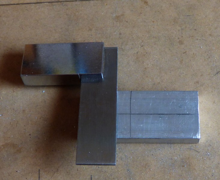
    With the holes cut, for the bearings,  I fitted one bearing halfway into one housing, and then put the two housings in the clamp on vice, and squeezed them together... The reason I did this, is because, the holes did not line up exactly, and work had to be done on the Ball Race Housings, to make them both the same size again... Having the two "joined" by the internal bearing, meant that this would produce an accurate re-sizing... It was only a matter of a couple of mm, but that would have made the pivot bar lopsided and the key just would not have worked.


Bearing "halfway in"...


Two blocks held on the same bearing, ready for "squaring up" 


 AfterI had completed the drilling, I, then had the job of making sure that all surfaces were "square" to each other.... this is essential, especially for the surface that is going to be the base to base, as the centre hole of the bearings, when fitted, need to be perfectly horizontal, for the rocker pivot to work properly and smoothly.   My hacksaw work was never any good, and I hated metal work at school, so you can imagine I had to spend some time working on the "squareness" with files, and the router on the drill stand.


 When I was happy that the blocks were square. I marked the "inside" edge with a centre punch, so that when separated, and put back together, the bearings would be in the correct position.

I then marked up for drilling the holes to be tapped to put the threaded studs into, to secure it to the base...


 Next it was time to put the holes in the bottom, to fix threaded studs, for fixing to the base of the key...
 Using my sliding mini vice work table, I mounted the blocks in the vice, and made sure they were "square" and to double check, I used the drill bit against the vertical side of the block, to ensure the drilling would be correct.


I then selected the tap and proceeded to tap the holes ready for the studs....


Once that was done, it was time to use the rotary wire brush, to give the "brushed aluminium" finish


Before brushing with the rotary brush


After brushing with the rotary brush


On completion of the re-sizing, I used my electric drill with a rotary wire brush, and gave the two Ball Race Housings a good brushing over, ending up with a "brushed aluminium look"... this gives the finished article a nice appearance, but also covers up any scratchmarks obtained when in the vice, or other work being done on them...

Having done all that, it was time to put the parts together, and make sure that it worked properly and then to work out how to fix them all in place


 The inside ends of the pivot bar, have some knurled lock nuts on them, to stop the bar from moving in, or out, of the bearings ( sideways movement is not conducive to good morse sending !)... These knurled lock nuts, were obtained, by purchasing 4 old radio knobs, with 1/4 inch shaft holes.... a hacksaw through the knob, and hey presto, you have a nice knurled lock nut  !


The knob, and "spark guard" come into the story now....

Once the fitting had been approved....  it was time to tap the front end of the rocker bar to take the threaded end of the knob, and to fit the "spark guard".....


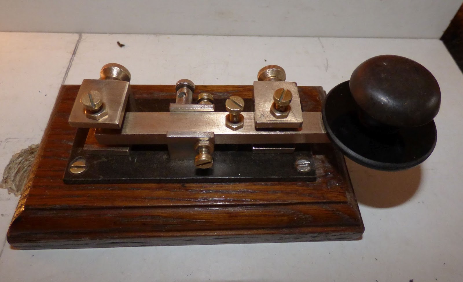
.The black one in the picture, (above)  was the initial choice from my own "stock" of bits and pieces... however I  previously mentioned the "local hardware store".. and whilst browsing in there, I noticed a solitary brass cupboard door, or drawer knob, with a brass "skirt"... only £1.00 ... and just the right size for my key...  which is the one you see in the final stages...

  As you can see, it looks just right, and the "skirt" is positioned under the front adjuster, with the "knob" from a brass sliding door bolt, to accomodate the "return spring"...


The black acryllic "spark guard" I obtained from a supplier on ebay... ..

( http://www.ebay.co.uk/itm/CLASSIKOOL-3MM-PERSPEX-ROUND-SQUARE-ACRYLIC-DISCS-PACK-10mm-200mm-4-COLOURS-/371034910941?var=&hash=item950fa1657f )


 Again, a pack of 10, for under £4.00..

. I  found the centre and drilled the necessary hole... put a bolt through, with a nut on it to lock it, and then fitted that to the drill... with the drill rotating it, I applied a file to the outer edges, to round them off, for comfort as I use the spark guard when I am transmitting. 


 It was now time to mark up a temporary base, to drill the pilot holes for the fixings.  I did this, by using a sticky label,  (sticky side down)... The pics below explain how it worked.

sticky labels in postion over the holes

Finding the holes through the paper with sharp pencil

Holes !

Turning up the edges so the sticky side is up

Sticky edges underneath.. now can locate the holes in template

Drilling the holes through the paper labels into a template

Temporary Template, with holes ready for drilling to oak base ( note nails to stop movement)

Temporary Oak Base... drilled to accept the Ball Race suports


Once I had ascertained that the parts fitted together on the old oak base,


 I had originally designed the key to have the gap adjuster at the rear... and so I made some temporary brid


Showing Temporary "bridges" and the Brass "skirt" from the Brass Knob under the rocker arm as a return spring holder.
Showing the temp adjuster screws. ready for trials and testing.


showing the brass skirt with return spring in position.
 Once the design had been proven to work on the temporary bridges, it was time to start work on the finished articles..... I selected brass bar for the uprights, because I could drill and tap both ends. rather than have the fixings on view on the top of the key base, and use a cross bar secured on top with two pan head bolts.  and the adjuster screws being very prominent


I cut four lengths of brass bar, and then proceeded to "square them up".. mounted in the mini vice, and using the rotary grinding wheel.  as previously described for the Ball Race Mountings..


After squaring them up.... I marked up the centres on all end faces... and drilled and tapped them,


Then I fitted them together, and placed them on the temporary oakd base.

..... having drilled and tapped the centre of the cross members, to take the adjusting screws.


 I obtained a nice Ash coloured base from another supplier on ebay,... who, unfortunately, has decided to discontinue selling placques/bases...


After locating all the parts on a soft carboard base


I used it as a template to temporary mark the new base before carefully re-measuring and marking up the new base, using sticky labels to protect the suface, and drilled the holes for the parts..


 I then used a "router" bit, on the underside to gouge out room for the studs to come through and fit the nuts on, without extending below the underside.

 Before final fitting, I decided to use another long screw, as a locking screw, for the main rocker shaft to the rocker pivot bar... Then fitted the bearings on to the end of the pivot bar,


....... then put it all together, on the new base,


 I had to go away and try it out, using a pair of croc clips with flying leads to another key... It worked fine... so it was back to the work shop for the finishing touches... a hole drilled through the rear, for the connecting wire... a couple fo swanky looking connecting posts and a couple of holes for the wires to pop up through ...


The finished key..... almost ........


The finished key..... almost.....  I was not happy with the way the fore and aft bridges had turned out, I was probably rushing the work, to get the key finished...  and I had already decided that I would replace the cross member with "real brass".. ( it was an alloy plated brass coloured strip ). and also to change from the pan head screws to studs with DOME cap nuts ...


 As you can see from the pics...  I also dismantled it, and gave all the parts a light brushing with the rotary wire brush to shine it all up....


Finally. I cut up a mouse mat, to fit to the underside of the base, to cover up the securing nuts, and to help prevent it from slipping across the desktop, when in use...

I am well pleased with the finished article, especially, as mentioned, I always hated metal work, and my only real "skill" is D.I.Y woodworking, and some ingenuity, and imagination... Plus, I suppose the desire to "have a go" and see how it turns out...


I made quite a few mistakes during the process, and, on one occasion a  10 second lapse of concentration, whilst using the grinding stone in the pillar drill stand, cost me three and a half hours extra work, re-working one of the bridges from scratch. !..

 Not forgetting that the "workshop" was/is a makeshift affair, and my inexperience of working to fine tolerances in metal did not help ! ! ..

A word of CAUTION..... Some of the methods and practices I used to make the parts, could be dangerous... and may not have been the "correct" health and safety ways of doing things... If you decide to follow this blog... you do so at your own risk... I take no responsibility for any injuries you cause yourself.   

You can see the finished key, below, with me transmitting on CWCOM  ( you can download CWCOM for free, and use for freee, from my other blogsite, which has several pages of useful information and step by step instructions including how to connect your key to your computer/laptop .... CWCOM was written for Windows, but also works on LINUX and MAC machines.... see the relevant pages on my blog .... )

 Link to my blog....
                                      https://morsepower.blogspot.co.uk/p/blog-page.html


Click on the little square, bottom right of the screen, for full screen experience... turn your sound up... and click the little arrow in the middle ! ! ... 


Tuesday, 17 November 2015

Signalling Equipment F-17 Morse Key Information

I have just received some very interesting historical information, about one of the keys in my collection.  The Signalling Equipment F-17... see this blog about it`s restoration...

 http://nemosphotography.blogspot.co.uk/2015/01/signalling-equipment-type-f-17-morse.html


For the benefit of researchers and those who maybe interested in the history, because they have one of these keys.. I am putting it on my blog as a separate item... ( I shall also incorporate it into the original blog to give more interest to the story )...

**********************************************************************************
The following information was provided by Tony/G4FAI.... who had seen my collection of Morse Keys on my Flickr page...

 https://www.flickr.com/photos/32369450@N02/22774770776/

On that picture, I have "guessed" the key was made about 1950... but it could well have been made much earlier, during World War II... 1939 - 1945. My key has the label Signalling Equipment on one end... and according to the information below, that was before 1946...

***********************************************************************************


I was interested in your Signalling Equipment F-17 as I wrote an article about the Morse products of that company for Morsum Magnificat some 23 years ago. I thought you might be interested in some of the details relating to your key.

It started with the photo of an “unknown” key in one issue followed by two letters in the next issue.
The first said it was a GPO single current key type F17 and that the cast base was copper-plated. 
The second writer said that he had used one of these keys in an Admiralty Wireless station in South West Tower, Admiralty. The key was  embossed with an Admiralty Pattern No.
My article, based on info from someone who had written a history of the company’s products describes it as a Commercial Key, open type frame, Diecast construction, Black and nickel finish, Silver contacts. Export code 279/DC/163/16. 
The same key was noted by another reader on a wooden base with a send/receive switch. It clearly had several lives. 
Signalling Equipment Ltd was bombed out of its premises in Old Street London in 1940 and moved to Potters Bar Middx where they produced Morse equipment for the war effort in various small vacant properties. They made keys, practice sets, buzzers and headphones. 
Some time before 1946 they became S.E.L.
 They later changed their name to J. Randall (Toys and Games) and later Merit.
 Among their toy products they continued making Morse practice sets, mainly for children.
********************************************************************************
Thanks, Tony..  
I have had a contact in Australia, who referst to the F-17 key with the export code number as the "type" number.. so it was obviously sent out there for use by the Australian Services. 

Tuesday, 3 November 2015

Another Vintage Key for me to restore

I am becoming addicted to ebay, and looking for "interesting" morse keys to see if I can get a good deal on them, and then  clean them up, and add them to my collection...

My latest one was advertised as Ex-R.A.F. but I am not so sure that it is... this is what it looked like when it arrived ...


As you can see, it looks forlorn, and dishevelled, dirty, and unloved... so I took it down to my workshop, and started to take it apart.... taking photo`s along the way, so I would know how to put it back together again, once I had finished..

First of all, I removed all the screws and knurled nuts,and removing the rocker arm,  being careful about the tension spring underneath the rocker arm....  This part makes me think it is "home brew" because the spring looks like it is snipped with a pair of pliers, and not a "commercial" type flush end.... also there is a small copper round headed rivet, that fits inside the spring, and resides in a cavity underneath the screw tensioner, on the rocker arm... 


The next part was to unscrew the bakelite base from the oak base,  and again... the screws seemed to have been "shortened" with pliers, rather than "correct size" which would have been fitted in a manufacturing factory made item.


With the skeleton now removed, I could access the screws underneath the bracket pieces... and another point here. two roundhead screws were used to fix the central rocker arm support....and these needed recesses into the oak base... again.this would not have been done in a factory envirnoment. probably the guy who made the key , did not have enough countersunk screws ! ! !..


The oak base looked very dirty, but it cleaned up with a bit of spit and polish.... YES !  . literally... !.. so the varnish must have been protected by the grime !.. although I did not use any polish... just the wet cloth, and some elbow grease...


And then it was time to get all the bits and pieces cleaned up.. I used some fine wet and dry to clean up the rocker arm... and then used a rotary wire brush, very lightly on all the screws and knurled nuts... held firmly in the vice on the bench... the metal brackets were given a light wire brushing where the contact threads are, but the flat surfaces were given a rub down on the wet and dry paper... It was used dry, as there was no real dust problem..

Once all the bits and pieces were looking good, it was time to refer to the pics on the camera, as I began to put it all back together again...It was a bit tricky trying to keep the spring with the rivet in it, in position whilst trying to re-locate the rocker arm, and insert the side screws for the pivot point.... but once that had been done, it was plain sailing.. Of course, I had to have a "spark guard" so that I can send with it. I think it "adds" to the beauty of this key as well as being practical.... and the whole job took just under 2 hours...


Below, is Before and After views......


On completion of the rebuild, I guessed the gap setting, which is done by either of the screws on the top of the front and rear brackets...but I set it on the rear one, and used the front one as a "stop".... when I got back indoors, I switched on CWCOM and plugged in the key... tightened up all the lock nuts, and away I went.... a real joy to use... very smooth in operation and makes good morse.

So, I am well pleased... Oh, by the way,   it cost me just under £21.00 including delivery, so another bargain key to add to my collection of 10 straight keys


Here is a short video of me sending with it....


Wednesday, 23 September 2015

My New Morse Key... !

PIC 001 New Key, on original Oak Base
My new key.  (Click on the pics for bigger version)

When I first got this key, PIC 001, I had already decided that I would do some modifications to it… principally to change the Oak Base, to a Mahogany base, so that it “matched” the other keys I have.  However, before I started to drill holes in the new base, I wanted to find out more about how the key was constructed, and how and why it would not hold it`s gap setting for more than a line or two of text.


     As can bee seen from the photo`s…PIC 001, 002, 003,  the key is an unusual design… the contact point is far away from the knob, and the spring adjustment “kind of” works in reverse, through a Horseshoe arrangement, where the spring compression is controlled by the knurled knob adjuster, just in front of the  sending knob.  In effect it can also alter the gap setting, because it works on the rocker arm itself. 

     The next obvious thing is the arrangement for the rocker arm to be supported from the rear end.  The “copper” fin that connected it to the mounting post was made from double sided PCB. Which, worked quite well, and probably does for most “normal” type sending.. For my style, I noticed that it has a tendency to twist on the horizontal plane, and also it shifted during use, making the rocker arm alter the contact gap, and thus corrupting my sending..

     On the original key, the wiring was through a hole in the back end of the base, to the appropriate points under the key… so another of my “modifications” was to put some terminal posts on the end of the base, to give a better, and more pleasing look, to the finish.

So, before doing any work on the new base, I needed to try things out, on the old black base, ….  PIC 004,…..


      Here, I replaced the PCB with a piece of brass sheet 25 mm wide and 1.6mm thick…( copied the size and style of original )…  It stiffened up the rocker arm, but still seemed to slide around on the horizontal… I kept trying different adjustments of the contact point, and the spring pressure, but to no avail… Eventually, I decided to double check the “square” ness, of the rear support pillar, and found it to be very slightly “out” of square.. A few minutes with a file, and I had it almost square.. ( I do not have any engineering equipment, or expertise, so I do my best with what I have ! ! ) it is probably not 100% square, but it is better than it was, and the rocker arm, now seems to sit more “level” across the base. I tried again, to send more than two lines of text… however, it still seemed to slide off to the right on the horizontal, and of course that changed the contact gap…. However, I tightened up the support bolts, and it seemed to improve it… so I proceeded on to my next modification….

      I decided that I would see if I could electroplate the brass strip from the support pillar to the rocker, with a copper finish, to replicate the original colour scheme…. Checked on YouTube for vids and then bought the necessary stuff… 1 pint of white vinegar,…..  I already had some copper, and a 9volt battery and some wires, and a short piece of copper pipe… so I put that aside while I did my next modification…
This one involved using a much longer piece of brass strip , twice as long as the original… to give a “long” look, and also to improve the “softness” of the spring effect it produces.  I also decided not to shape the piece into a V shape, as I thought that by keeping it 25mm wide all the way to the rocker, it would be less likely to twist on the horizontal axis…so I just "rounded" the corners where it joins the rocker arm proper...  and it worked fine on the black base… so.. Now I am ready to put all onto the new Mahogany base… I did my layout on paper, stuck to the base, and then drilled the holes for the rear support pillar… working forward and making sure the contact point was in the correct place, and then the spring tension horseshoe.

     Once it was all together, I was very pleased with the “new look”… and the key was given extensive testing...BUT again, the sideways movement on the horizontal axis came into play… and this is what I did to eliminate that…

      First, I tried to see how much movement there was, by physically pushing the rocker arm from left to right horizontally, and that movement showed me that the “play” was in the actual drilled holes of the support pillar and the cap on the top of the rocker arm extension… It appears that the maker used 4mm engineering screws, but drilled the holes one size too big…… This is not necessarily a problem for “normal” use, as mentioned in the beginning.. Where the sender actually lightly grips the sending knob, during his sending… My style is to use the first two fingers of my right hand, and “tap” the morse on the “spark shield” of the sending knob,… not actually holding the knob at any time…. This produces a sideways movement across the spark shield, and subsequently moves the rocker arm horizontally.  Eureka moment ! …

     How to solve the problem…? ? ? ? ?  . One thought that I had, was that the rocker arm adjustment contact point,  was too small,… just the end of the screw thread.. And so I thought about inverting that adjuster, and using the head of the machine screw as the contact point… this also provided a much flatter surface for cleaning and levelling the base contact point, with fine wet and dry paper…. I also raised up the spring tension horseshoe slightly as the rocker arm hit the underside and did not give adequate clearance….. Then I simply tried to tighten up the nuts on the support pillar,  as tight as I could but this did not work… again, I had the idea that, maybe, the surfaces were not “true” so I spent a few minutes with a file and sorted that out… all the while thinking how I could make sleeves for the holes…

     First idea was to use the tin foil from a margarine tub… cut into a strip of suitable size, and wrapped around the screw shaft… it kinda worked,… but was difficult to get in place… so a MK II version was needed… something a bit more substantial…. The tinfoil from a steak pie !… same principle ,… same problem….

     Then.. Eureka moment again… MK III version….for the small top plate I needed a very small section , so I decided to hammer some copper wire flat, into a very thin strip, which just about made the correct size to  fashion a tube washer or sleeve to fit…. It took me about 3 hours to finish the first one… but it worked,… fortunately,… so I then proceeded with the second one and that took about an hour…. .

     It took so long because I had to fashion the small tube/sleeve, then insert it into the hole, and then remove it, to file out the inside, repeatedly, until I could get the machine screw to pass through it… fortunately I had the right size 4mm round file available… in … out… in … out… repetative work, but in the end I managed to get them both to be just right… … The holes in the main support pillar were also 4.5 mm…but I could not use the copper wire, as the holes were about 25mm long and this needed to be sleeved too… however, it was quite easy to fashion the sleeves using the aforementioned steak pie tinfoil, suitably cut to size and rolled around the machine screw shank, until it “just” fitted in the holes in the support pillar…

      Whilst all this desk work was going on…. The brass strip was quietly being electroplated in a jam jar in the kitchen…. Although not perfect… I am quite pleased with the result… washed and dried, it was now time to put it all together again…. And this time it seems to have gone well… there is no horizontal movement across the rocker arm… even when I push and pull hard, it does not move… so the time and effort spent in doing the copper wire tube/sleeve work, and re-surfacing of the other parts, has really paid off… 

       I have also fitted a couple of gold plated terminal posts, as mentioned, and the necessary cuts for the wire connections below…

See PIC 005 and 006 for the finished key, with all modifications.


PIC 005 New Key with new base and modifications


PIC 006 New Key with new base and modifications


Overall, I am pleased with the way it has turned out…. The key feels more “solid” and workmanlike… and with some minor tweeks on the gap and spring, and some long practice sessions, will, I am sure become a favourite key to me.

Here is a short video of how I use the key.... You can see I do not "hold" the key at all... and this caused the sideways movement referred to in the text above....

Put on your phones, or turn your speakers on.... click on the square to give full screen...