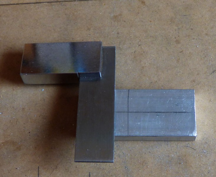
After doing so many refurbishments, and the alterations to the Welsh Torsion Bar Straight Key ( My New Morse Key ).... I thought I might have a go at making my own designer straight morse key... and so the story begins.... My initial thoughts were for it to be similar to the Kent style key.. with the ball races for the pivot point... so I decided on the size of the bearings, by starting with the actual pivot rod size, which would have to be 6mm or 1/4inch round brass stock... I looked on ebay for some "cheap" bearings, as I did not know what the outcome of my work would be... i.e. if I decided that I could not proceed, then the bearing price would have been "in the bin" along with any other materials.
I found a real bargain.... a pack of 10 bearings, 6 x 19 x 6mm for just under £4.00 including posting ! ! .. ( http://stores.ebay.co.uk/heavends?_trksid=p2047675.l2563 )
As I did not have a workshop, the next problem I had to solve, was how and where, was I going to do the work necessary, to produce the morse key... Fortunately, we have a BIG "shed" at the bottom of the garden.. that we only used for storage... it had power for an electric drill, lighting, and heating.. It also had a fridge in a small corner area... here, I used my imagination, and used a couple of wooden pasting tables... One as the base of the work bench, laid on top of the fridge, and the other to act as the "floating end" legs, by using it in an "inverted V" formation,... I used a couple of big nails to nail it together, and it became quite firm... On top of that, I used a couple of loft flooring boards for the actual workbench surface... ensuring that there was an overlap at the front and the end, for attaching a clamp on vice. .
 |
| The Workshop !... showing the Pillar drill stand with home made sliding work table. |
Next I decided I needed to have a "Pillar Drill Stand".. to fit my electric drill into, so I could drill vertially and accurately into the work pieces... This item cost me just under £25.00 from a local hardware shop.... about the same price on Ebay, but I do like to help out the small local hardware shop when I can... .. Once I had it at home, I made a sliding work table, out of some white melamine shelving boards,........
and another, separate one with a screwed down mini vice, to hold any work pieces that needed drill or grinding work...
 |
| View of the "sliding mini vice" work table |
|
 |
| End on view of the sliding mini vice work table. |
|
A set of 4 small grinding wheels, to fit into the drill chuck, and some router bits, were added to the tools list, and also I obtained a set of Tap & Die, to make the screw threads in the work pieces as needed. I already had drill bits, hacksaws, files, hammers etc.. so, now I was ready to start work...
My orignal design, was to use a kind of "sliding wedge" at the rear end of the rocker, to adjust the gap, but because of my limited experience of working with metal, I could not make the system work, so I abandoned that, in favour of a "flat tounge" with a screw down adjuster.
I started off with the pivot housing, through which the 1/4 inch brass round stock would go, and ground the semi-circular parts for the housing, giving it a nice appearance. This took some time, as I had to be very careful not to try to take too much of a "bite" with the grinding wheel.
 |
| Cutting the block, and marking up |
 |
| Setting the piece on a wood block for grinding |
 |
| Final location and marking for the grinding process |
 |
| Fixing the block on the worktable ready for grinding with the pillar drill |
 |
| Two views of the finished block |
After that, the next part was to decide where it would be fitted along the rocker arm base....
 |
| Laid on it`s side on the bench to decide on the location of the pivot block in relation to the other parts |
.......................and drill holes in the rocker arm base, and also into the pivot
housing,
then using the appropriate tap, put a thread into the pivot
housing, and secure it with screws...
I chose this method, against soldering, because I did not have a big enough, hot enough, soldering iron to do heavy brass solder joints. .. I could have used the gas jet on the gas cooker, but trying to get two pieces of extremely hot brass into the correct position , and hold them there, whilst the solder set, seemed to be a bit too dangerous for me ! ! ! ...
The next stage was to make the Ball Race Housings. I used aluminium bar for these, as I could not find a supplier on ebay, that could do the size that I needed in Brass... however, I think it has turned out for the best, because they look really good, and the aluminium was easy to work too !...
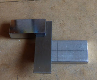 |
| Marking up the Ball Race Housing |
Once I had the basis of the housings all squared up... I located the
bearing, and marked up where I wanted the bearing housing hole to be
cut... and did that work on the Pillar Drill Stand...
 |
| As you can see, not too accurate with the centre punch ! ( caused extra work later on ! ! ) |
 |
| Drilling the pilot hole, ready for three further enlargements to correct size |
|
 |
| Drill selection |
 |
| Drilling pilot hole in both blocks |
With the holes cut, for the bearings, I fitted one bearing halfway into one housing,
and then put the two housings in the clamp on vice, and squeezed them
together... The reason I did this, is because, the holes did not line up
exactly, and work had to be done on the Ball Race Housings, to make
them both the same size again... Having the two "joined" by the internal
bearing, meant that this would produce an accurate re-sizing... It was
only a matter of a couple of mm, but that would have made the pivot bar
lopsided and the key just would not have worked.
 |
| Bearing "halfway in"... |
 |
| Two blocks held on the same bearing, ready for "squaring up" |
AfterI had completed the drilling, I, then had the job of making sure
that all surfaces were "square" to each other.... this is essential,
especially for the surface that is going to be the base to base, as the
centre hole of the bearings, when fitted, need to be perfectly
horizontal, for the rocker pivot to work properly and smoothly. My
hacksaw work was never any good, and I hated metal work at school, so
you can imagine I had to spend some time working on the "squareness"
with files, and the router on the drill stand.
When I was happy that the blocks were square. I marked the "inside" edge with a centre punch, so that when separated, and put back together, the bearings would be in the correct position.
I then marked up for drilling the holes to be tapped to put the threaded studs into, to secure it to the base...
Next it was time to put the holes in the bottom, to fix threaded studs, for fixing to the base of the key...
Using my sliding mini vice work table, I mounted the blocks in the vice, and made sure they were "square" and to double check, I used the drill bit against the vertical side of the block, to ensure the drilling would be correct.
I then selected the tap and proceeded to tap the holes ready for the studs....
Once that was done, it was time to use the rotary wire brush, to give the "brushed aluminium" finish
 |
| Before brushing with the rotary brush |
 |
| After brushing with the rotary brush |
On completion of the re-sizing, I used my electric drill with a rotary wire brush, and gave the two Ball Race Housings a good brushing over, ending up with a "brushed aluminium look"... this gives the finished article a nice appearance, but also covers up any scratchmarks obtained when in the vice, or other work being done on them...
Having done all that, it was time to put the parts together, and make sure that it worked properly and then to work out how to fix them all in place
The inside ends of the pivot bar, have some knurled lock nuts on them, to stop the bar from moving in, or out, of the bearings ( sideways movement is not conducive to good morse sending !)... These knurled lock nuts, were obtained, by purchasing 4 old radio knobs, with 1/4 inch shaft holes.... a hacksaw through the knob, and hey presto, you have a nice knurled lock nut !
The knob, and "spark guard" come into the story now....
Once the fitting had been approved.... it was time to tap the front end of the rocker bar to take the threaded end of the knob, and to fit the "spark guard".....
.The black one
in the picture, (above) was the initial choice from my own "stock" of bits and
pieces... however I previously mentioned the "local hardware store"..
and whilst browsing in there, I noticed a solitary brass cupboard door,
or drawer knob, with a brass "skirt"... only £1.00 ... and just the
right size for my key... which is the one you see in the final
stages...
As you can see, it looks just right, and the "skirt" is
positioned under the front adjuster, with the "knob" from a brass
sliding door bolt, to accomodate the "return spring"...
The
black acryllic "spark guard" I obtained from a supplier on ebay... ..
( http://www.ebay.co.uk/itm/CLASSIKOOL-3MM-PERSPEX-ROUND-SQUARE-ACRYLIC-DISCS-PACK-10mm-200mm-4-COLOURS-/371034910941?var=&hash=item950fa1657f )
Again, a
pack of 10, for under £4.00..
. I found the centre and drilled the
necessary hole... put a bolt through, with a nut on it to lock it, and
then fitted that to the drill... with the drill rotating it, I applied a
file to the outer edges, to round them off, for comfort as I use the
spark guard when I am transmitting.
It was now time to mark up a temporary base, to drill the pilot holes for the fixings. I did this, by using a sticky label, (sticky side down)... The pics below explain how it worked.
 |
| sticky labels in postion over the holes |
 |
| Finding the holes through the paper with sharp pencil |
 |
| Holes ! |
 |
| Turning up the edges so the sticky side is up |
 |
| Sticky edges underneath.. now can locate the holes in template |
 |
| Drilling the holes through the paper labels into a template |
 |
| Temporary Template, with holes ready for drilling to oak base ( note nails to stop movement) |
 |
| Temporary Oak Base... drilled to accept the Ball Race suports |
Once I had ascertained that the parts fitted together on the old oak base,
I had originally designed the key to have the gap adjuster at the rear... and so I made some temporary brid
 |
| Showing Temporary "bridges" and the Brass "skirt" from the Brass Knob under the rocker arm as a return spring holder. |
 |
| Showing the temp adjuster screws. ready for trials and testing. |
 |
| showing the brass skirt with return spring in position. |
Once the design had been proven to work on the temporary bridges, it was time to start work on the finished articles..... I selected brass bar for the uprights, because I could drill and tap both ends. rather than have the fixings on view on the top of the key base, and use a cross bar secured on top with two pan head bolts. and the adjuster screws being very prominent
I cut four lengths of brass bar, and then proceeded to "square them up".. mounted in the mini vice, and using the rotary grinding wheel. as previously described for the Ball Race Mountings..
After squaring them up.... I marked up the centres on all end faces... and drilled and tapped them,
Then I fitted them together, and placed them on the temporary oakd base.
..... having drilled and tapped the centre of the cross members, to take the adjusting screws.
I obtained a nice Ash coloured base from another supplier on ebay,... who, unfortunately, has decided to discontinue selling placques/bases...
After locating all the parts on a soft carboard base
I used it as a template to temporary mark the new base before carefully re-measuring and marking up the new base, using sticky labels to protect the suface, and drilled the holes for the parts..

I then used a "router" bit, on the underside to gouge out room for the studs to come through and fit the nuts on, without extending below the underside.
Before final fitting, I decided to use another long screw, as a locking screw, for the main rocker shaft to the rocker pivot bar... Then fitted the bearings on to the end of the pivot bar,
....... then put it all together, on the new base,
I had to go away and try it out, using a pair of croc clips with flying leads to another key... It worked fine... so it was back to the work shop for the finishing touches... a hole drilled through the rear, for the connecting wire... a couple fo swanky looking connecting posts and a couple of holes for the wires to pop up through ...
 |
| The finished key..... almost ........ |
|
|
The finished key..... almost..... I was not happy with the way the fore and aft bridges had turned out, I was probably rushing the work, to get the key finished... and I had already decided that I would replace the cross member with "real brass".. ( it was an alloy plated brass coloured strip ). and also to change from the pan head screws to studs with DOME cap nuts ...
As you can see from the pics... I also dismantled it, and gave all the parts a light brushing with the rotary wire brush to shine it all up....
Finally. I cut up a mouse mat, to fit to the underside of the base, to cover up the securing nuts, and to help prevent it from slipping across the desktop, when in use...
I am well pleased with the finished article, especially, as mentioned, I always hated metal work, and my only real "skill" is D.I.Y woodworking, and some ingenuity, and imagination... Plus, I suppose the desire to "have a go" and see how it turns out...
I made quite a few mistakes during the process, and, on one occasion a 10 second lapse of concentration, whilst using the grinding stone in the pillar drill stand, cost me three and a half hours extra work, re-working one of the bridges from scratch. !..
Not forgetting that the "workshop" was/is a makeshift affair, and my inexperience of working to fine tolerances in metal did not help ! ! ..
A word of CAUTION..... Some of the methods and practices I used to make the parts, could be dangerous... and may not have been the "correct" health and safety ways of doing things... If you decide to follow this blog... you do so at your own risk... I take no responsibility for any injuries you cause yourself.
You can see the finished key, below, with me transmitting on CWCOM ( you can download CWCOM for free, and use for freee, from my other blogsite, which has several pages of useful information and step by step instructions including how to connect your key to your computer/laptop .... CWCOM was written for Windows, but also works on LINUX and MAC machines.... see the relevant pages on my blog .... )
Link to my blog....
https://morsepower.blogspot.co.uk/p/blog-page.html
Click on the little square, bottom right of the screen, for full screen experience... turn your sound up... and click the little arrow in the middle ! ! ...