
Pages

Saturday, 18 April 2015

Home Made Paddle Morse Key - (almost) no soldering !

I have never really been interested in "side swiper" type keys... always considered them to be something of a "toy", and  "for amusement purposes only"... Always been a dedicated fan of the straight key, in all its various manufacturing types and forms... to me, they are "history", and things of beauty to the eye... ( most of them , anyway...).. I have a collection of 8 straight keys, which are detailed in earlier blog pages... if you are interested in Morse Keys, then you might find them interesting too !.. However, I digress, as the saying goes... this item is about how I came to make a paddle key... The idea came from seeing one on YouTube... but that was just "an idea"... and not really pursued... until,... I heard about a guy on CWCOM, who had made his key out of an old wire coathanger, and an even older piece of scrap wood...  ( pic below )..


so.... I thought.. "oh well, let`s see if I can make one, and see if I can operate it when it is made "... I know there are many radio amateurs that use these keys, exclusively, and there is a "culture" of which make of key is the best, and also which type... single or twin paddle... well, this one that I have made, can be used in either format... single or twin paddle,.. and you will be able to see that during the construction phase on this blog...

I can send with it... but not good enough to hold a qso ( conversation ). with it... so I am not going to give a video demo when I have finished this piece.... anyway.. as I mentioned in the first lines of the first paragraph...it`s "for amusement purposes only"  LOL !

OK.. first of all...  What do you need to make a paddle key like mine ?  well view the pic below...it`s all there ... Oh yes, in the title it says "(almost) no soldering"... the only soldering required, is for the 3.5 mm jack plug... but if you are clever, and have one already wired up from another job/equipment (earphones).. then you won`t need to solder anything...


In the above pic, is all the bits needed to make the key...   on the left there is a length of 30 amp ( cooker wiring ). 3 core solid copper "twin and earth"... I used the blue and the brown wires stripped down, to make the paddles, as you will see later.. the "earth" is a shade too thin and bendy...

Note.. there are two plugs at the top of the pic,... one is a 5amp round pin. ( the one I used ). and the other is the standard U.K. 13amp mains power plug. with the square pins.. you can use either, so long as you have the relevant wall socket plate, to fit the pins.

First of all, you need to remove the pins from the plug,... and using some Araldite, on the pins just under the little "sticky out" pins ( that stop it twisting in the plug ). insert them into the face plate, ensuring that the earth pin is fitted first, to give the safety plate a shift, so you can insert the other two pins... when inserting the other two, you will notice they have black insulation on them...


 this MUST have some araldite on it, along with the brass part under the "sticky out" pins... DO NOT PUT THE ARALDITE ON THE FACE PLATE it will be drawn into the plug contacts, and may insulate them ! ! .. The reason for making sure the araldite goes on the black plastic insulation is, that, if not, then the pin will tend to move in the socket, especially when using twin paddle operation. They need to be secure....

Note... make sure the holes in the pins are facing in the right directions.... the single pin (earth pin) needs to be aligned to "face the front" i.e. down between the other two pins... to insert the single paddle...   The two other pins, need to be aligned "east/west" so that you can insert screws for the gap adjustment. 


Don`t forget, to allow about a couple of hours for the araldite to set off, before proceeding... I know it`s a pain.. but if you don`t and you start twisting the pins around, they will not be secure...

Once you have waited for them to set off,...you can proceed to make the single paddle using some of the blue or brown copper wire, as mentioned.... Cut off about 6 inches ( i think that`s about 150mm in forren measurements).. If you have a vice available, cut a small part of the insulation off one end, and insert the copper wire in the vice, to pull off the main part of the insulation with a pair of pliers. If you want, you can fashion a curly bit on one end, like I did,.. or bend it into a triangle or square shape... your choice...you could even leave it straight !..  You now need to insert the other end in the single "earth" pin... and adjust the length before screwing down tight...

Two screws are needed to fit into the smaller pins... Originally I used two small wood screws that fitted into the holes on the pins.. with the heads in the centre as contacts.. but I intended to, and did, buy a small pack of 4  3mm pan head bolts in brass as these "look the part"..


Now you have the basics of the key put together.. all you need is the paddle, and the wiring...

Wiring up is simple... drill a hole in the back box on one edge... feed in your connection cable ,... bare off the ends,... and simply connect up using the screw connections on the back of the socket... ( see ... no soldering ! !  ! ! )..


Just before securing down the face plate (paddle key)... if plug in your key to CWCOM ... or if you have a multi-meter, you can confirm that you have made the connections properly, by "shorting out" the single pin, to the other pins in turn... once you are satisfied they are properly connected to the 3.5mm jack, you can secure down the faceplate and fix your paddle....


Whilst the araldite was setting off, you could have been making the paddle, but it is best to wait, and do it now...

below is a choice of paddles I made, after first using the single paddle


To make this single paddle , I used a paper clip, bent in half, then soldered at the folded end ( for more solid screw down connection), and then, holding the preformed "curly" bit in the vice... and the paperclip in a pair of pliers, rans some solder down to join them... 


To change the single paddle into a twin paddle, you need to form a pair of paddle shapes from the copper wire, or , as I did , from a couple of large paper clips... again. I doubled over the end going into the pins on the key plate, and soldered where necessary... Trial and error will give you the best combination and something to do when it rains  ! ! ! ! ... making new paddles... 


You will, of course, have realised that using the twin paddle version needs the plate to be turned around 180 degrees, so that the connecting wire is coming out at the top of the key....

and there you have it... It was great fun making it... and fun trying to figure out how to use it... I enjoyed the challenge, and will "play" with it fromt time to time... but doubt if I willl ever be convinced that this is a "proper morse key"....


Sunday, 15 February 2015

Admiralty Pattern 7681 - Re-Build ! !

My original Admiralty Pattern 7681 morse key, as seen in this pic,


Has been radically changed several times, for experimental purposes !.. however, I recently discovered a source of very nice quality "Mahogany type" bases....


 and thought that it might be a good idea to re-build that key, onto a new base...  ( the Birds Eye Maple base, looked nice, but had some damage to it, and also it was rather large and cumbersome, rendering the key to an unused status symbol ! )...I also wanted to  return the rocker arm to it`s original size again... The original rocker arm was well and truly worn out, and no good for a rebuild, so obtained some square brass bar from a supplier on Ebay... When it arrived it had a bad scratch mark on it, from where it had slipped in the vice when it was cut !.. ( as you can see on this pic...)...


 never mind.. I may be able to fix that... we`ll see...

   After it was cut to size, I then marked up the balance points, using a sticky label, and securing the rocker arm between the pointed adjustable pivot points.  Once I was satisfied that they were in the correct place, I used my small drill bit, to "dent" the brass, and give the points some place to lodge.... the next thing to do was to measure up and mark the drill points... one for the rear gap adjuster, the next for the spring tensioner, then on the other end, the contact point, and the knob.

The rear adjuster needed to be threaded,  so I had to purchase a set of reamers on ebay... very quick supply, ( next day ).. so no hanging about... I drilled the holes, with a pilot hole first, and then to size, and reamed the adjuster thread into it... the underside of the spring adjuster needed to be "countersunk" to allow the maximum "pull" on the thread, bringing the top of the spring into the rocker arm... at the other end, it was a case of finding a small brass machine screw, with sufficient length, to act as the front contact point... again, I used the reamer to put in a thread, so it would be "tight" when finally fitted and screwed right down... the knob is threaded internally, so all I needed was a clearance hole for the machine screw to fix the knob...


A refinement, I thought, taken from a bakelite AP7681 is a flat sprung metal connector to ensure the rocker arm is electrical connected to the main frame,... this required a very small screw in the underside of the rocker arm...  ( you can see the sprung metal connector in this pic )...


Once all the bits and pieces had bee worked on, and fixed to the rocker arm,... it was time to consider the positioning of the main frame, onto the base.... to help to keep the base free from scratches, and to give me somewhere to "mark up".. I cut a piece of plain paper to size, and stuck it down with some blu tack on each corner...


I then found the centre line... and placed the rocker and main frame onto it... Once I was satisfied that it was in the correct place... I used a pencil to mark the holes that I needed to drill for the fixing screws, to come from underneath...


Where I could, I used a small "phillips" screw driver in the hole and tapped it with a hammer, to indent the paper, and also the wood beneath.


I then drilled pilot holes, to check that they were in the correct locations, and then drilled them according to the size of the screws that would be needed....


 Some of the screws needed to be "countersunk"  underneath, so that they would have enough thread above to fix the main frame.... also needed to be countersunk to keep the under surface level, for the final fitting of the non-slip mat.


The front and rear contact points were then located, marked, and drilled in the same way... To make sure the front contact point was directly underneath the rocker arm contact point.. I used a rule, on edge, and used the edge as a "vertical", to mark the paper where the centre of the contact point, ( and drill hole ) should be


..a channel was cut in the bottom of the base for a connecting wire from the front contact to the separate terminal.


The rear terminal does not have any wired connection,... but still needed to be secured by a screw from below.

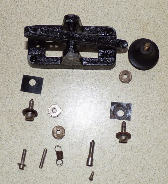
Having got all the bits and pieces in their correct places... it was time to take them off again, to remove the paper, and dismantle completely, the rocker arm... this had to be done, to enable me to try to remove the scratch mark, first mentioned. I did this by running the naked rocker arm back and forth over some very fine wet and dry paper,  (keeping it dry).. until the mark had disappeared... doing this has also put a nice shiny surface onto the rocker arm, so I did all four sides ....


 time now to finally put all the bits back together again...

The (almost) finished key........

 a quick check with a multimeter to make certain the connecting wire was, indeed, connecting the front rocker to the terminal,  proved ok... Also did a quick test with a "flying lead" to another morse key, to check that it was indeed working... before I added the final touches, the non-slip mat, ( thin washing up sponge sheet !)


 and, of course, a new connecting lead and jack plug.


The finished key......


Below is a short movie showing the key in action..(you can make it full screen by clicking on the little square)


Just a final note.... I do not have a workshop, nor do I have any engineering background/skills, just my desktop in the lounge, with a 12volt battery drill, and a clamp on vice, to work with...

Thursday, 12 February 2015

Connection Box for Morse keys or Audio equipment

UPDATED 22/11/18

For some time now I have had an "improved version" of the "connection box" shown in this blog page.

It consists of 20 chassis mounted stereo sockets, fixed into a "plastic conduit" box as used for mounting electric cables in buildings..
The sockets are mounted on the "loose" capping, so that the backing can be permanently fixed to some point on the desk/wall

I now have 15 straight keys attached to my USB to Serial Converter in this manner ! ..


Having 8 morse keys connected to my laptop, via the USB/Serial Connector cable, via twin stereo adapter plugs, was a messy solution,...

Messy Junction !


 I wanted to tidy my desktop, and decided to make a connection box to plug all the keys into... The box I chose was rather larger than necessary, but will suffice to show the construction process, and details of the work as it progressed....

Two designs of box presentation
Depending on the space and location of the connection box, in its "in use" position, depends on the "face" where the socket holes will be drilled....


I decided that the side view would be convenient, and would sit nicely in a small space beside my radio on my desktop... so I found the centre line, then spaced the holes accordingly...

Inside the box, there are ridges, to support small pcb`s which makes the thickness of the box a little too much for the outer fixing to grip the socket sufficiently, so I had to "pare away" or thin an area behind each hole.......


The next job was to carefully twist the lugs on the sockets by 90 degrees. 


The reason for this, is , to facilitate threading a bared copper wire through each socket, after soldering to the first one.


Once the first one is soldered, it is easy to thread on the others, before fitting them into the holes in the box,....


As each one is fitted, into the box, they slide along the wires, into positon fairly easily... soldering first, or trying to wire up after fitting, would have been very tiresome,


After soldering, tighten up the lock nuts, and trim off the excess wire,

solder on the external lead, after tying a knot in, to prevent pulling it away, when in use...

 The finished box only needs the lid screwing on.....

Make sure the connections on the "fly lead" jack, are compatible with the socket on the equipment you intend to use this box on, and follow through to "mimic" those connection on the sockets on this box.... A multimeter, with croc clip, and a spare jack would be useful for detemining the correct connections throughout.

Disclaimer.....

You are responsible for any damage to your equipment, if you decide to follow this blog instruction.. I accept no responsibility for damage to your equipment.


Monday, 12 January 2015

Signalling Equipment Type F-17 morse key refurbishment

Signalling Equipment F-17 Morse Key waiting for refurbishment


Signalling Equipment F-17 Morse Key waiting for refurbishment

                        NOTE : -  CLICK ON THE PICS TO ENLARGE  !

Yet another refurb job !... I must be addicted to them.... saw this one on ebay, looking pretty sorry for itself, and decided to rescue it, and try and bring it back to life... At the time, I did not know the make or model/type of it...

I got my small kit of screwdrivers etc, out on the bench, and proceeded to dismantle the key... not too difficult, but I did want to make sure I kept all the parts in one place !...


Signalling Equipment F-17 Morse Key in parts for cleaning

 Once I had all the parts off, I started to clean the main body and the rocker.

It was quite dirty, and the rocker arm was very stiff, almost siezed with dried dirt, so I got my old toothbrush out, some washing up liquid and a drop of water,.... ten minutes later, it was drying on the radiator, but not before I noticed a label on the back end...


Signalling Equipment F-17 Morse Key rear end showing label

At first, I though it said something like,.. S Smalling Equipment... then a light came on.. and I thought it might be Signalling Equipment.. so I did what I always do... Google Images and put in Signalling Equipment Morse Key.... sure enough there was a pic of one the same as my new acquisition !.. so I now have a name and type... Signalling Equipment F-17...

. not sure of the date, so if anyone knows... please get in touch .... I reckon it is about 1940 to 1950`s due to the black crackle paint finish on it...

UPDATE... (17 November 2015 )


**********************************************************************************
The following information was provided by Tony/G4FAI.... who had seen my collection of Morse Keys on my Flickr page...

 https://www.flickr.com/photos/32369450@N02/22774770776/

On that picture, I have "guessed" the key was made about 1950... but it could well have been made much earlier, during World War II... 1939 - 1945. My key has the label Signalling Equipment on one end... and according to the information below, that was before 1946...

***********************************************************************************


I was interested in your Signalling Equipment F-17 as I wrote an article about the Morse products of that company for Morsum Magnificat some 23 years ago. I thought you might be interested in some of the details relating to your key.

It started with the photo of an “unknown” key in one issue followed by two letters in the next issue.
The first said it was a GPO single current key type F17 and that the cast base was copper-plated. 
The second writer said that he had used one of these keys in an Admiralty Wireless station in South West Tower, Admiralty. The key was  embossed with an Admiralty Pattern No.
 
My article, based on info from someone who had written a history of the company’s products describes it as a Commercial Key, open type frame, Diecast construction, Black and nickel finish, Silver contacts. Export code 279/DC/163/16. 
 
The same key was noted by another reader on a wooden base with a send/receive switch. It clearly had several lives. 
 
Signalling Equipment Ltd was bombed out of its premises in Old Street London in 1940 and moved to Potters Bar Middx where they produced Morse equipment for the war effort in various small vacant properties. They made keys, practice sets, buzzers and headphones. 
 
Some time before 1946 they became S.E.L.
 
 They later changed their name to J. Randall (Toys and Games) and later Merit.
 
 Among their toy products they continued making Morse practice sets, mainly for children.
 
**********************************************************************************
 
End of Update.


Anwyay, after it was dried, I went to the shed and squirted the rocker arm ends with copious quantities of WD40... and worked the rocker until it fell freely, as is should to...( another 15 minutes )! !... dried off the excess and proceeded to put it back together again...

Checking the pic on Google Images, I noticed that the tension spring was held directly vertical under the adjuster by a bar across the base of the key.... on my version the spring had been screwed on to the rear contact connection, underneath... When I came to re-fixing it... I used a matchstick to replace the bar..( will do the bar later, when I find suitable strong wire )..  there were no difficulties in putting the parts back on the base, however, it is possible to mis-align the contact points, and they can be slightly adjusted by just slackening off the locking nuts on the base, underneath, and locating them correctly... also note that the contacts have fibre washers to insulate them from the main body.....


Signalling Equipment F-17 Morse Key after cleaning 


Signalling Equipment F-17 Morse Key with added Spark Guard


As you can see from the original pics, and the re-furb pics, the original key does not have a "spark guard" under the knob....  I use the spark guard when I am keying, and find that using the knob is not very good for me,. so I have fitted a spark guard to my re-furb... I think it looks quite good !... certainly works well,....


Signalling Equipment F-17 Morse Key with added Spark Guard


On testing the key, it will probably need a smaller tension spring, as the one fitted is a little on the long side... not sure if it is the original, but..... it`ll do for now...

I went on ebay to find a nice mahogany base, which is now fitted.... I had to drill a hole in the rear end and down the centre, to accept the wiring.......  Looks pretty smart!!  and will go back there for some more to fit to some of  my other 6 keys along my bench, to be used in QSO`s on CWCOM  ( Morse over the internet ) program.. ( MRX software - FREE )


Signalling Equipment F-17 Key mounted on Mahogany Base
 For those interested, the base was purchased from AFM WOODWORK located in Birmingham, England... on ebay http://stores.ebay.co.uk/afmwoodwork/_i.html?rt=nc&_pgn=2&_ipg=48
He has a wide range of placques/plinths in various shapes and types of wood finish. He will also accomodate your sizes if you contact him..... Recommended if you want to smarten up your old key(s).....

Update ....  (17 November 2015) unfortunately AFM Woodwork are no longer supplying base/plinths to order... they are discontiuing this, and are selling only their remaining stock.... If anyone knows of a U.K. supplier..... please contact me. 

If you are a "sparker" or "Tel"  or " Teleg" from anywhere in the world, then you can use CWCOM you don`t need a licence, and you don`t need a ham radio call,... just the enthusiasm, and passion for Morse Code or CW communication.  Look forward to QSO soon...... de GEMS QRV K 

You can watch the video on Full Screen.. Click on the box at the bottom right corner....... and you may need to adjust the volume....


Friday, 29 August 2014

Hi Mound HK-708 Refurbishment

I use CWCOM, a program that enables us to communicate using CW , or Morse, either from the keyboard, or from a "proper" morse key connected to a laptop or PC.  An excellent program that can be made to work with Linux OS as well as Windows OS. It enables those of like mindedness, to practice and preserve a very old, and original DIGITAL, method of communication, world wide, without the use of high powered transmitters and receivers... No antenna, ( aerial ) in the garden... and no Amateur Radio Licence is needed... All standards of user are welcome... Over a period of 18 months, I have made over 220 contacts, world wide.. some only briefly, but others have become "regular" and interesting contacts..I have already posted a video of me operating my Hi Mound HK-705 from my car, as a "mobile" operator... and recently a friend in Japan made contact with me, whilst he was travelling on the Bullet Train, doing 186MPH.... I have also made contact with a guy in the Bay of Biscay, on his Catamaran, whilst he travels to the mediterranean for his summer vacation.

One of my original contacts, Mike, who lives in Harrogate, Yorkshire,...  sent me his old Hi Mound HK-708 straight key, because he has arthiritis and cannot use it any more, he uses a paddle key.. On arrival, the key certainly needed some cleaning... so I just took it to bits, and gave it a good scrub with an old toothbrush, and some soapy water,...I repacked the bearing caps,  using Flora Margarine, and put it all back together....

 Looking very smart, then I started to get the setting of the tension spring and the gap, so that it was easy to use.... Unfortuately, the big knob on it, became very slippery, due to the way that I send morse....(  tapping on the knob, instead of actually holding it in the "correct manner". !..}   . I normally use the spark gap skirt, to transmit on, but the HK-708 did not have one... Doing some research, I found a supplier of plastic discs,

www.AcrylicCraft.co.uk

and I ordered 5 discs with a 3 mm centre hole...


after arrival, two days later, ( excellent service ).. I decided that I needed to "round off" the outer edge, so I put a 3mm brass bolt and nut in the centre hole, and ran up my battery powered drill, with it in the chuck, using a file, and some fine wet and dry paper, I had the required round edge all finished within about 5 minutes... You can see the rounded edge on the one fitted to the HK-708 in this pic...


When I came to fit the skirt, it was about the same size as the knob, and so it was difficult to use... I decided to swap the knob with another key, which knob was made from a wooden drawer knob from the local DIY shop !.. Because of the bend in the rocker arm of the HK-708. I needed to secure the skirt and knob, on top of a securing nut just under the skirt... which you can just see on the video... Resetting the tension spring and the gap, did not take very long, and you can now view the video of me sending a test transmission using the key..   It works very well, and will probably become my favourite to use key for a while....

Here is the video... I hope you can read morse ! ! ...( speed is about 22 words per minute )....