 |
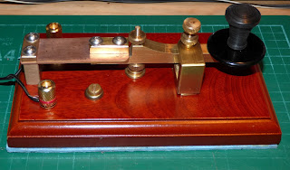
| PIC 001 New Key, on original Oak Base |
When I first got this key, PIC 001, I had already decided that I would do some modifications to it… principally to change the Oak Base, to a Mahogany base, so that it “matched” the other keys I have. However, before I started to drill holes in the new base, I wanted to find out more about how the key was constructed, and how and why it would not hold it`s gap setting for more than a line or two of text.
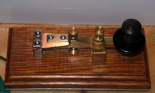
As can bee seen from the photo`s…PIC 001, 002, 003, the key is an unusual design… the contact point is far away from the knob, and the spring adjustment “kind of” works in reverse, through a Horseshoe arrangement, where the spring compression is controlled by the knurled knob adjuster, just in front of the sending knob. In effect it can also alter the gap setting, because it works on the rocker arm itself.
The next obvious thing is the arrangement for the rocker arm to be supported from the rear end. The “copper” fin that connected it to the mounting post was made from double sided PCB. Which, worked quite well, and probably does for most “normal” type sending.. For my style, I noticed that it has a tendency to twist on the horizontal plane, and also it shifted during use, making the rocker arm alter the contact gap, and thus corrupting my sending..
On the original key, the wiring was through a hole in the back end of the base, to the appropriate points under the key… so another of my “modifications” was to put some terminal posts on the end of the base, to give a better, and more pleasing look, to the finish.
So, before doing any work on the new base, I needed to try things out, on the old black base, …. PIC 004,…..
Here, I replaced the PCB with a piece of brass sheet 25 mm wide and 1.6mm thick…( copied the size and style of original )… It stiffened up the rocker arm, but still seemed to slide around on the horizontal… I kept trying different adjustments of the contact point, and the spring pressure, but to no avail… Eventually, I decided to double check the “square” ness, of the rear support pillar, and found it to be very slightly “out” of square.. A few minutes with a file, and I had it almost square.. ( I do not have any engineering equipment, or expertise, so I do my best with what I have ! ! ) it is probably not 100% square, but it is better than it was, and the rocker arm, now seems to sit more “level” across the base. I tried again, to send more than two lines of text… however, it still seemed to slide off to the right on the horizontal, and of course that changed the contact gap…. However, I tightened up the support bolts, and it seemed to improve it… so I proceeded on to my next modification….
I decided that I would see if I could electroplate the brass strip from the support pillar to the rocker, with a copper finish, to replicate the original colour scheme…. Checked on YouTube for vids and then bought the necessary stuff… 1 pint of white vinegar,….. I already had some copper, and a 9volt battery and some wires, and a short piece of copper pipe… so I put that aside while I did my next modification…
This one involved using a much longer piece of brass strip , twice as long as the original… to give a “long” look, and also to improve the “softness” of the spring effect it produces. I also decided not to shape the piece into a V shape, as I thought that by keeping it 25mm wide all the way to the rocker, it would be less likely to twist on the horizontal axis…so I just "rounded" the corners where it joins the rocker arm proper... and it worked fine on the black base… so.. Now I am ready to put all onto the new Mahogany base… I did my layout on paper, stuck to the base, and then drilled the holes for the rear support pillar… working forward and making sure the contact point was in the correct place, and then the spring tension horseshoe.
Once it was all together, I was very pleased with the “new look”… and the key was given extensive testing...BUT again, the sideways movement on the horizontal axis came into play… and this is what I did to eliminate that…
First, I tried to see how much movement there was, by physically pushing the rocker arm from left to right horizontally, and that movement showed me that the “play” was in the actual drilled holes of the support pillar and the cap on the top of the rocker arm extension… It appears that the maker used 4mm engineering screws, but drilled the holes one size too big…… This is not necessarily a problem for “normal” use, as mentioned in the beginning.. Where the sender actually lightly grips the sending knob, during his sending… My style is to use the first two fingers of my right hand, and “tap” the morse on the “spark shield” of the sending knob,… not actually holding the knob at any time…. This produces a sideways movement across the spark shield, and subsequently moves the rocker arm horizontally. Eureka moment ! …
How to solve the problem…? ? ? ? ? . One thought that I had, was that the rocker arm adjustment contact point, was too small,… just the end of the screw thread.. And so I thought about inverting that adjuster, and using the head of the machine screw as the contact point… this also provided a much flatter surface for cleaning and levelling the base contact point, with fine wet and dry paper…. I also raised up the spring tension horseshoe slightly as the rocker arm hit the underside and did not give adequate clearance….. Then I simply tried to tighten up the nuts on the support pillar, as tight as I could but this did not work… again, I had the idea that, maybe, the surfaces were not “true” so I spent a few minutes with a file and sorted that out… all the while thinking how I could make sleeves for the holes…
First idea was to use the tin foil from a margarine tub… cut into a strip of suitable size, and wrapped around the screw shaft… it kinda worked,… but was difficult to get in place… so a MK II version was needed… something a bit more substantial…. The tinfoil from a steak pie !… same principle ,… same problem….
Then.. Eureka moment again… MK III version….for the small top plate I needed a very small section , so I decided to hammer some copper wire flat, into a very thin strip, which just about made the correct size to fashion a tube washer or sleeve to fit…. It took me about 3 hours to finish the first one… but it worked,… fortunately,… so I then proceeded with the second one and that took about an hour…. .
It took so long because I had to fashion the small tube/sleeve, then insert it into the hole, and then remove it, to file out the inside, repeatedly, until I could get the machine screw to pass through it… fortunately I had the right size 4mm round file available… in … out… in … out… repetative work, but in the end I managed to get them both to be just right… … The holes in the main support pillar were also 4.5 mm…but I could not use the copper wire, as the holes were about 25mm long and this needed to be sleeved too… however, it was quite easy to fashion the sleeves using the aforementioned steak pie tinfoil, suitably cut to size and rolled around the machine screw shank, until it “just” fitted in the holes in the support pillar…
Whilst all this desk work was going on…. The brass strip was quietly being electroplated in a jam jar in the kitchen…. Although not perfect… I am quite pleased with the result… washed and dried, it was now time to put it all together again…. And this time it seems to have gone well… there is no horizontal movement across the rocker arm… even when I push and pull hard, it does not move… so the time and effort spent in doing the copper wire tube/sleeve work, and re-surfacing of the other parts, has really paid off…
I have also fitted a couple of gold plated terminal posts, as mentioned, and the necessary cuts for the wire connections below…
See PIC 005 and 006 for the finished key, with all modifications.
 |
| PIC 005 New Key with new base and modifications |
 |
| PIC 006 New Key with new base and modifications |
Overall, I am pleased with the way it has turned out…. The key feels more “solid” and workmanlike… and with some minor tweeks on the gap and spring, and some long practice sessions, will, I am sure become a favourite key to me.
Here is a short video of how I use the key.... You can see I do not "hold" the key at all... and this caused the sideways movement referred to in the text above....
Put on your phones, or turn your speakers on.... click on the square to give full screen...


